SID (Sound)
Contents | Back: Interrupts | Next: Printed Circuit Board
We have very little space left on the PCB, so we can add only one other IO device. I don't want to add any CRT graphics to my system but i think it definitely needs some 80s vintage sound generation. A C64's SID with its support circuitry barely fits on the board. The only problem is that a SID needs a 9V supply. I will cheat a little bit and generate the 9V from the 5V with a modern DC-DC boost converter.
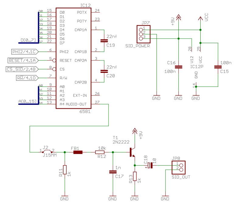
Schematic
The analog output buffer stage is, once again, directly borrowed from the C64 schematic.
Breadboard construction
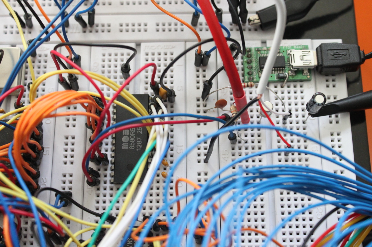
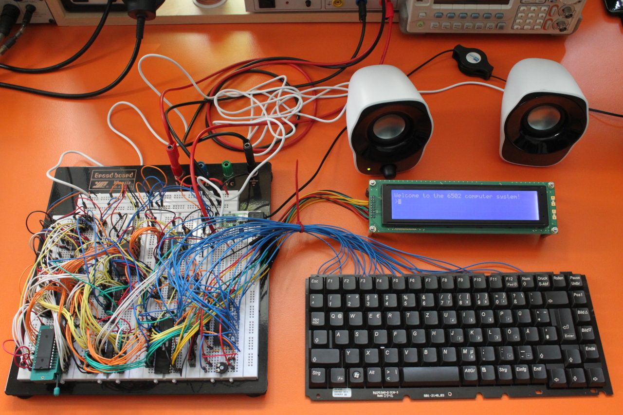
The 9V come from an external power supply. This will be replaced by a DC-to-DC boost converter module on the PCB. A small active speaker is connected to the SID output.
Program
The program for this part implements a simple synthesizer that can be played with the keyboard. In an endless loop it scans the keyboard and if a key is pressed its key code is translated into a frequency value. Then the first SID oscillator is set to this frequency and its gate bit is set. The oscillator then executes the ADS phases of the envelope and we here a sound. If the key is released, the gate bit is cleared. The oscillator executes the R phase of the envelope and the sound ceases. notes_lo points to an array of the low bytes of the frequencies and notes_hi points to an array of the high bytes.
                lda #$09
                sta SID_VOICE1_AD
                lda #$8A
                sta SID_VOICE1_SR
                lda #$0f
                sta SID_MODE_VOLUME
@read_keys:     jsr keys_update
                jsr keys_getchar
                bne @key_pressed
                lda #$20
                sta SID_VOICE1_CTRL
@key_pressed:   cmp #$1b
                bne @check_note
                lda #$00
                sta SID_MODE_VOLUME
                rts
@check_note:    cmp #'a'
                bcc @read_keys
                cmp #('z' + 1)
                bcs @read_keys
                sec
                sbc #'a'
                tax
                lda notes_hi,x
                beq @read_keys
                sta SID_VOICE1_FREQ_H
                lda notes_lo,x
                sta SID_VOICE1_FREQ_L
                lda #$21
                sta SID_VOICE1_CTRL
                jmp @read_keys
PCB
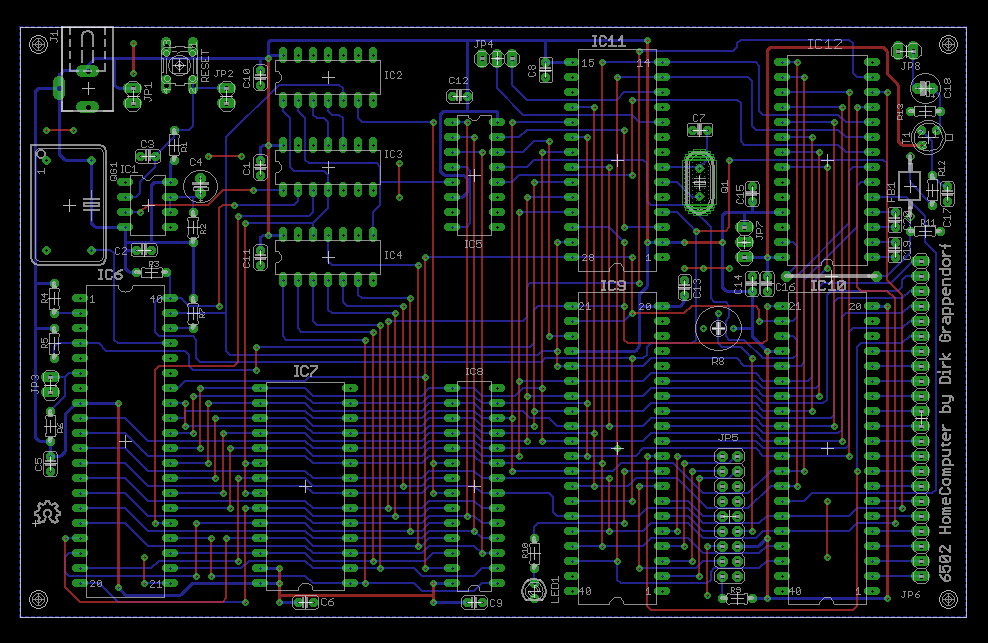
See the jumper wire below the SID (IC 12)? I completely overlooked that I could route this signal around the chip. In the next part you can see the final PCB design.
Weblinks
- Wikipedia
http://en.wikipedia.org/wiki/MOS_Technology_SID - Datasheet
http://pdf.datasheetarchive.com/indexerfiles/Datasheets-SW3/DSASW0043786.pdf - SID in depth information
http://sid.kubarth.com/ - SID programming
http://codebase64.org/doku.php?id=base:sid_programming