Sunrise Alarm Clock
A wake-up light. Built with Elixir and Nerves. Running on a Raspberry Pi Zero.
The Hardware | The Software | Testing
The simulator
The sunrise alarm clock contains a software simulation of the real hardware. This simulator presents the state of the simulated hardware on a web page and the developer can interact with it. Since the software can be started on the developers local machine, this can drastically reduce the turnaround time during development.
With Elixir and Nerves, implementing the simulator is a piece of cake. Since every hardware module is implemented as a separate process, we can replace these processes with simulations, as long as they accept the same messages as the original ones.
Simulation can be done on different levels. We could either simulate our own hardware modules (like Buttons or Lcd), or we could simulate the underneath Nerves processes (like GPIO or I2C).
Simulating the Nerves processes gives us the oppurtunity that all of our own code is executed, even during simulation. The downside is, that the development of an I2C or GPIO simulation is much more complicated. So in the current version of this software, i wrote simulations for the higher level modules Buttons, Lcd, Leds, Settings and Touch. This is sufficient when we focus on the development of the business logic.
How to run the Simulator
First of all if you haven't already done so, you need to install Erlang and Elixir. Please refer to this Elixir Installation Guide to find instructions for your specific environment.
Next we need to install the Nerves framework. The Nerves Installation Guide can be found on the Nerves web site.
Then clone the GitHub repository for this project and enter the directory of the firmware application. You also need to create a copy of the provided local config file example.
$ git clone https://github.com/grappendorf/sunrise-alarm-clock.git
$ cd sunrise-alarm-clock/sunrise-alarm-clock-nerves/fw
$ cp config/local.exs.example config/local.exs
Now you can finally install the project dependencies and start the system in the default development (simulation) mode. Compilation happens during the first time you execute mix phx.server, which takes some time before the application starts up.
$ mix deps.get
$ mix phx.server
...
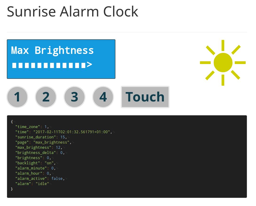
13:41:49.479 [info] Running UiWeb.Endpoint with Cowboy using http://localhost:4000You can then access the simulators web page in your browser: http://localhost:4000/sim The clocks settings web page can be accesses through the URL: http://localhost:4000
The top part of the simulator shows the input and outout elements. The big box at the bottom shows all the current attributes of the system state.
Testing
The following tests (i prefer the term specifications) are implemented with ESpec and some parts of the specification code is omitted. You can execute all of the specifications by executing the mix task espec in the apps/fw directory:
$ mix espec
How to test the Input/Output-Modules
When we want to run automated specifications for our hardware modules, we have the problem that this hardware doesn't exist on our development machines. For example the Lcd module uses the I2C module to write to the LCD via the I2C bus. So when we test this module on our local development workstation, this surely will gonna fail. We clearly need a way to replace these low level functionality with something else.
Mocking
As with most modern languages, Elixir allows us to replace functions with mocks. These mocks are then executed when their original counterpart is called and can return prefabricated values. We can also check if these mocked functions got executed during our tests.
Here is the complete specification of the Leds module:
defmodule LedsSpec do
  use ESpec
  import WaitHelper

  before do
    allow I2C |> to(accept :start_link, fn _, _ -> {:ok, :i2c} end)
    allow I2C |> to(accept :write, fn _, _ -> nil end)
    Leds.start_link
  end

  finally do: GenServer.stop :leds

  describe "start_link/1 initializes the LED dimmer controller" do
    it do
      wait_for do
        expect I2C |> to(accepted :write, [:i2c, <<0x01, 0x00>>])
        expect I2C |> to(accepted :write, [:i2c, <<0x02, 0x00>>])
        expect I2C |> to(accepted :write, [:i2c, <<0x03, 0x00>>])
        expect I2C |> to(accepted :write, [:i2c, <<0x04, 0x00>>])
        expect I2C |> to(accepted :write, [:i2c, <<0x05, 0b00001101>>])
      end
    end
  end

  describe "backlight(:on) switches the backlight on" do
    before do: Leds.backlight :on
    it do: wait_for do: expect I2C |> to(accepted :write, [:i2c, <<0x05, 0b00001101>>], count: 2)
  end

  describe "backlight(:off) switches the backlight off" do
    before do: Leds.backlight :off
    it do: wait_for do: expect I2C |> to(accepted :write, [:i2c, <<0x05, 0b00001100>>])
  end

  describe "light(value) sets the alarm LED brightness to value" do
    before do: Leds.light 42
    it do: wait_for do: expect I2C |> to(accepted :write, [:i2c, <<0x04, 42>>])
  end
end
This option has some drawbacks. First of all, mocks tend to let implementation details of the functions under test leak into the test code. If for example you change the implementation during a refactoring, your tests will most likely fail and need to be refactored too.
Next look at the specification for the backlight(:on) function. Because i set the backlight LED to on in the initialization function, the function call I2C.write(:i2c, <<0x05, 0b00001101>>) will be executed two times in the end. So i need to expect the I2C.write() function to be called two times, despite the fact that it is called only once in the backlight() function. This makes the spec harder to understand and leads to misinterpretations.
One last peculiarity is the need for a wait_for macro. Since the functions in the Leds module cast messages to the Leds process, they return immediately. So we cannot expect the I2C functions to be called directly after a call to the Leds functions. The wait_for executes its do block repeatedly until the expectations succeed or until a timeout has occurred.
This last problem is not only related to mocking but to any form of testing where the subject under test is performing some actions asynchronously, like the following one.
Simulation
Another option is to replace the low level IO processes of Nerves with our own ones, that simulate the functionality of the connected hardware. As said before, as long as our fake processes understand the same messages as the original ones and respond to them in the same way, there should be no issue.
When writing simulation modules, always try to keep them as simple as possible. We don't want to mimic every detail of the hardware, only their behaviour at the interface level. For example: we are not using the input register of the PCA9530 controller, so we dont' implement its access in our simulator. The PCA9530 simulator is a direct translation of the datasheet and looks like this:
defmodule Pca9530 do
  use ExActor.GenServer, export: :pca9530

  defstart start_link do
    initial_state %{ led0: :off, led1: :off, pwm0: 0, pwm1: 0}
  end

  defcall state, state: state, do: reply state

  defcall write(data), state: state do
    set_and_reply (case data do
      <<0x02, pwm>> -> %{state | pwm0: pwm}
      <<0x04, pwm>> -> %{state | pwm1: pwm}
      <<0x05, 0 :: size(4), led1 :: size(2), led0 :: size(2)>> ->
        %{state | led1: led_mode(led1), led0: led_mode(led0)}
      _ -> state
    end), :ok
  end

  defp led_mode(0b00), do: :off
  defp led_mode(0b01), do: :on
  defp led_mode(0b10), do: :pwm0
  defp led_mode(0b11), do: :pwm1
end
As you can see, Elixir's pattern matching on binary data comes in quite handy when developing embedded hardware.
And here are the specifications that use this simulator:
defmodule LedsSpec do
  use ESpec
  import WaitHelpers
  import ExActorHelpers

  before do
    allow I2C |> to(accept :start_link, fn _, _ -> Pca9530.start_link end)
    Leds.start_link
  end

  finally do
    GenServer.stop :leds
    GenServer.stop :pca9530
  end

  describe "start_link/1 initializes the LED dimmer controller" do
    it do
      wait_for do
        expect(Pca9530.state().led0) |> to(eq(:on))
        expect(Pca9530.state().led1) |> to(eq(:pwm1))
        expect(Pca9530.state().pwm0) |> to(eq(0))
        expect(Pca9530.state().pwm1) |> to(eq(0))
      end
    end
  end

  describe "backlight(:on) switches the backlight on" do
    before do: Leds.backlight :on
    it do: wait_for do: expect(Pca9530.state().led0) |> to(eq(:on))
  end

  describe "backlight(:off) switches the backlight off" do
    before do: Leds.backlight :off
    it do: wait_for do: expect(Pca9530.state().led0) |> to(eq(:off))
  end

  describe "light(value) sets the alarm LED brightness to value" do
    before do: Leds.light 42
    it do: wait_for do: expect(Pca9530.state().pwm1) |> to(eq(42))
    it do: wait_for do: expect(Pca9530.state().led1) |> to(eq(:pwm1))
  end
end
I think that this is much better to read because it precisely expresses our expectations of the system behaviour. We only need to stub the I2C.start_link/2 function so that our own I2C process is returned.
The main drawback with this method is, that our PCA9530 simulator can of course contain programming errors. So i repeat my hint: keep your test code as simple as possible.
How to test the Reducers
Testing the reducers is the easiest thing to do. Since the reducer functions are pure functions with no side effects, we simply prepare a given store state and call a reducer with this state and an action. We then compare the new state with the desired outcome. Lets look for example at the reducers that are called when button one is pressed on any page:
let reduce: &LogicUiReducers.reduce/2

describe "button 1 action cycles through the pages" do
  it do: expect(reduce().(%{page: :clock}, {:button, 1})).to eq(%{page: :alarm_active})
  it do: expect(reduce().(%{page: :about}, {:button, 1})).to eq(%{page: :alarm_active})
  it do: expect(reduce().(%{page: :alarm_active}, {:button, 1})).to eq(%{page: :alarm_hour})
  it do: expect(reduce().(%{page: :alarm_hour}, {:button, 1})).to eq(%{page: :alarm_minute})
  it do: expect(reduce().(%{page: :alarm_minute}, {:button, 1})).to eq(%{page: :sunrise_duration})
  it do: expect(reduce().(%{page: :sunrise_duration}, {:button, 1})).to eq(%{page: :max_brightness})
  it do: expect(reduce().(%{page: :max_brightness}, {:button, 1})).to eq(%{page: :time_zone})
  it do: expect(reduce().(%{page: :time_zone}, {:button, 1})).to eq(%{page: :clock})
end
For each page we specify the page to go to when the button was pressed.
Here is a more complex example, where we specify the behaviour of our alarm logic.
let reduce: &LogicAlarmReducers.reduce/2
let time: nil
let state: %{
  alarm_active: true,
  alarm_hour: 14,
  alarm_minute: 23,
  alarm: :idle
  sunrise_duration: 10
  time: time()
%}

describe "alarm_check action checks if an alarm must be started" do
  context "when the current time is before the sunrise time" do
    let time: time_at 12, 46, 0
    it "the alarm state should stay idle" do
      expect(reduce().(state(), :alarm_check).alarm).to eq(:idle)
    end
  end

  context "when the current time is after the sunrise time" do
    let time: time_at 16, 11, 0
    it "the alarm state should stay idle" do
      expect(reduce().(state(), :alarm_check).alarm).to eq(:idle)
    end
  end

  context "when the current time passed the sunrise time" do
    let time: time_at 14, 13, 1
    it "the alarm state should switch to sunrise" do
      expect(reduce().(state(), :alarm_check).alarm).to eq(:sunrise)
    end
  end
end
Instead of testing only some concrete examples, a better option could be to use a property based testing tool like ExCheck . With ExCheck we can specify the behaviour of our system for all possible system states and actions. We can for example explicitly state that for every time that is before any sunrise start time, the alarm state should stay idle. And for any time that passes any sunrise start time, the alarm state should switch to sunrise (in reality though, only a (configurable) number of random test points will be checked).
How to test the Subscribers
For the subscribers we have the same options as for the input/output modules. You can either implement simulators for the lower level processes or you can use the stubbing mechanisms of a testing framework.
Subscribers are a somewhat easier to test than input/output modules, since in most cases a single subscriber contains exactly one single side effect.
Conclusion
On this last page of my article i wanted to demonstrate that developing thoroughly tested embedded software with Elixir and Nerves can be a great pleasure (instead of a necessary evil).
The easiness with which we can write our specifications to test our design, the terse programming style of Elixir which almost always avoids the need to write boilerplate code together with the robustness of the Erlang platform, lets us write better embedded software in a shorter amount of time.
Currently Elixir/Nerves has the downsides that we need to run a Linux kernel and also that the Erlang-VM has a big footprint. So we need a microprocessor and the necessary amount of RAM to run our system.
With the Gulon VM we may in the future get an Erlang VM, that can run on systems with much more constrained resources.
The boot time of the Linux kernel could also be a problem. On a Raspberry Pi Zero, it takes about 12 seconds until the Erlang VM is loaded and executes our Nerves application. On some devices like an IP telephone this is not a big deal, since the users are accustomed to see a "Booting up..." message on these devices. But with other devices like the alarm clock in this project, users might expect them to be instantaneously ready for use.
But as microcontrollers become more and more powerful, these problems will definitely disappear.