LCD Display
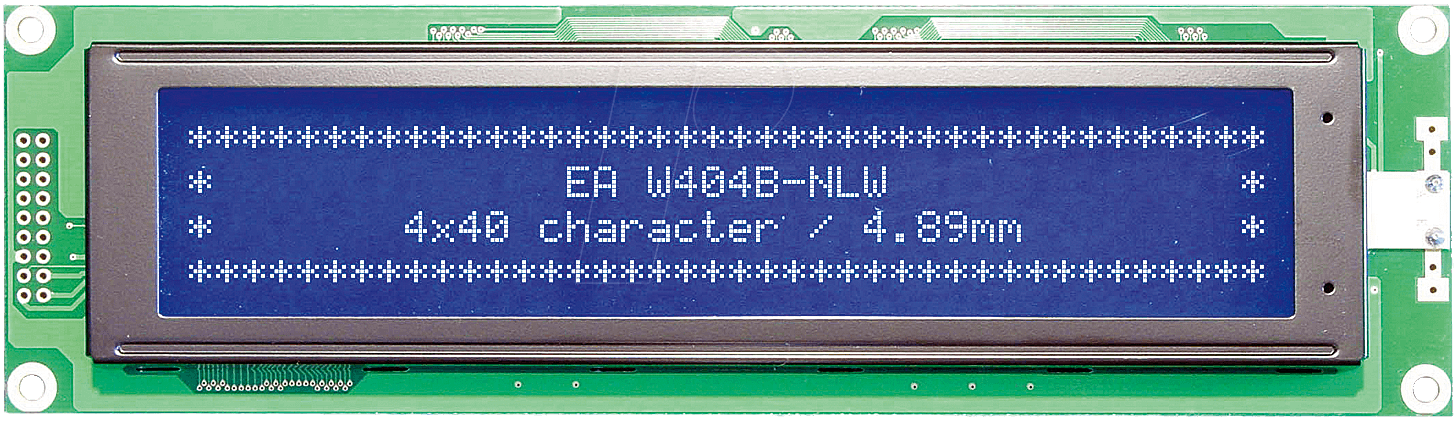
When we have a working VIA interface, adding an LCD with a HD44780 controller is straightforward. Connect four data lines (or eight if you wan't to use the 8 bit mode), the RS line and the enable line to a port of the VIA. If you want to use a 4 row display, then you need to connect 2 enable signals, since these displays contain two independent controller chips. In most cases we don't need to read from the display, so we can connect the R/W signal directly to ground and save one IO pin. In addition to this control lines we need the power supply, a trimmable contrast voltage and possibly a power supply for the back-light. In my case (using an Electronic Assembly Blue Line display EA W404B-NLW ) a 150 ohm resistor is appropriate.
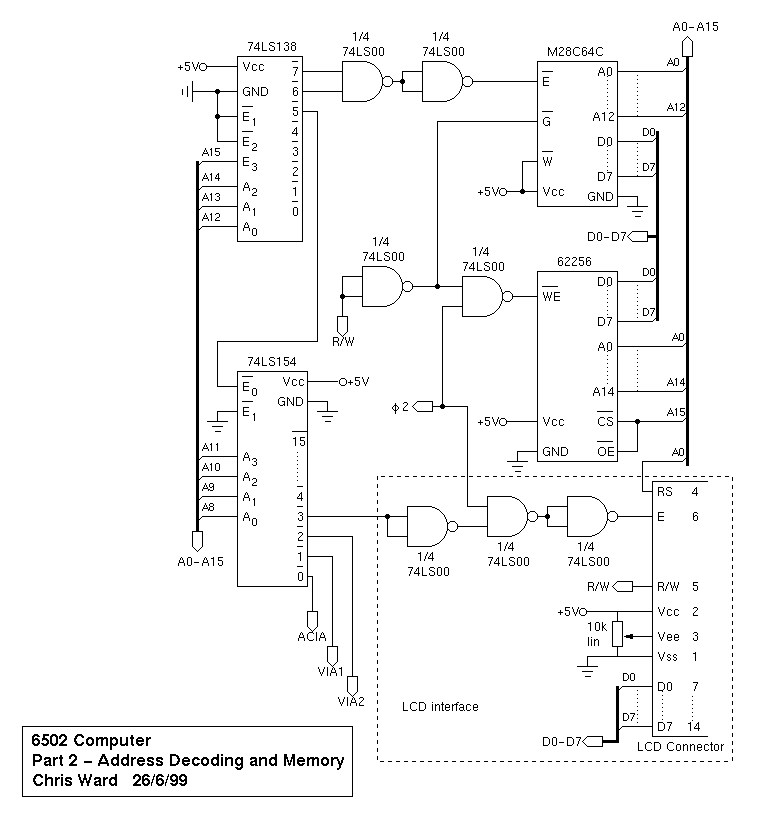
Another option to add an LCD display is to connect it directly to the data and address buses as Chris Ward has done it in his design . Keep in mind that you need to take the ϕ2 signal into account, as we have done it in the RAM chip select circuit.
Schematic

Breadboard construction
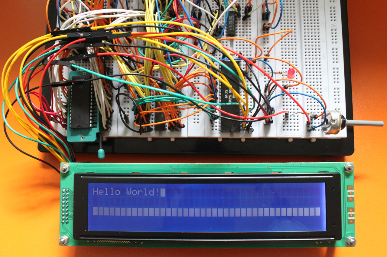
I simply added the display to the VIA IO pins and connected the power lines.
Program
The software listing is too long to show here and isn't that much interesting. It uses bit banging and delay loops to drive the LCD signal lines. On the Internet you find quite some information on how to program the HD44780 controller and the initialization sequence that is needed if you want to use the 4-bit data mode. The LCD module should contain functions for printing characters and strings, setting the cursor position and clearing the display. Here is a small example how these functions can then be used:
jsr lcd_init
ld16 R0, msg_welcome
jsr lcd_puts
ldx #0
ldy #1
jsr lcd_goto
lda #'>'
jsr lcd_putc
jsr lcd_cursor_blink
PCB

As you can see, I moved the ACIA to the top of the board and placed the VIA below. We now have enough space to add two more ICs. I also added a flood filled ground plane to the bottom layer.