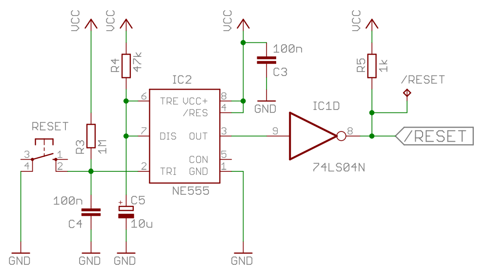
Reset Circuit
When a computer is powered up, the input voltage is rising slowly. So for a couple of clock cycles, correct functioning of the processor may not be guaranteed and it's best to delay the program execution until the environment has stabilized. Today there exist specialized controllers for this (which also check for brown out conditions), but for a historical 6502 computer we borrow the reset circuitry directly from the good old C64. It is a simple 555 one shot multivibrator that keeps the reset line low for approx. 0.5 seconds after power on. I've added a button that pulls the trigger pin of the 555 low to perform a manual reset.
Archive.org hosts the C64 service manual , which includes a description of its reset circuit .
And here you find two pages of the C64 schematics .
Schematic
Breadboard construction
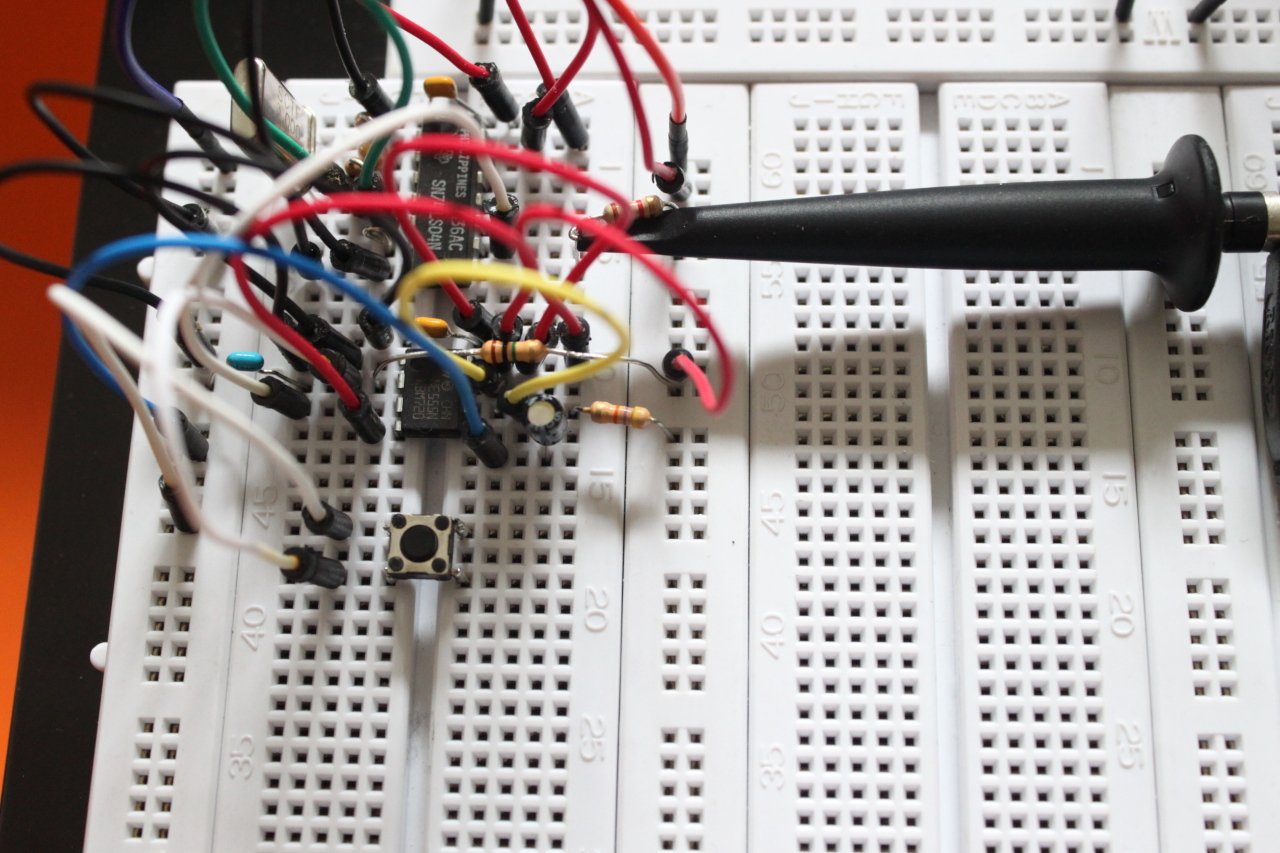
I placed the 555 directly below the clock circuit, because we need one of the three remaining inverters.
Measurements
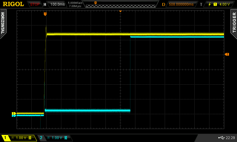
Channel one is the power supply, Channel two is the low active reset signal. As you can see, after powering on the reset line stays low for about 560ms. Pressing the reset button also results in a reset pulse > 0.5 seconds.
PCB
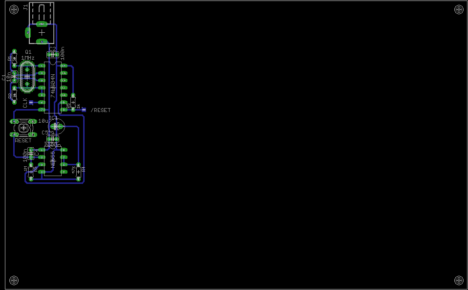
The reset circuitry is placed below the clock generator.