ACIA (Serial interface): Hello World!
At this point we need some kind of input/output facility. Being able to send commands to the computer and receiving status values back greatly simplifies further hardware and software development.
Back in the 1970s/1980s you would have connected some keys and LEDs ( 7-segmend displays ) to your system. Later on you may have replaced the keys with a full fledged keyboard and the LEDs with a LCD ( HD 44780 character display ) or your television CRT.
Cross-developement, meaning that you use another computer to write and debug the software for the system under development, was no affordable option for the hobbyist.
Today we always write the code for our microcontroller systems on a development workstation and transfer the generated code with some kind of programming device directly into the microcontroller in a circuit (in-system-programming or ISP). Protocols like JTAG let us debug the code directly in the running system.
So my approach is to use a 6551 ACIA device (which includes a serial interface) and a FT232 based serial to USB converter. Together with a minimal monitor program in the EEPROM, this enables us to send commands to our 6502 system (e.g. write to memory or IO-devices) and query the contents of the processor registers and memory locations.
When we connect some RAM to our computer, we are then also able to transfer programs into the RAM and start them, so we no longer need to always reprogram the EEPROM every time we want to try something out.
Here is the (Rockwell) datasheet of the 6551 ACIA .
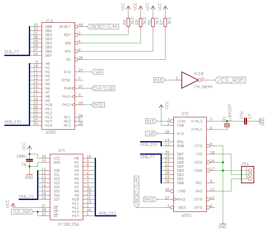
Schematic
First of all we need some minimal address decoding logic. Until now the processor sees the EEPROM on each of the 64k addresses. Now we enable the EEPROM only if A15 is high. This is done by inverting A15 to generate a low active /CS_ROM signal for the upper 32k. If A15 is low we'll enable the ACIA (which is then mirrored many times into the first 32k). A0 and A1 are used to select one of the four ACIA registers. Pay special attention to the /CTS signal, which needs to be connected to ground in order to enable the transmitter module.
Breadboard construction
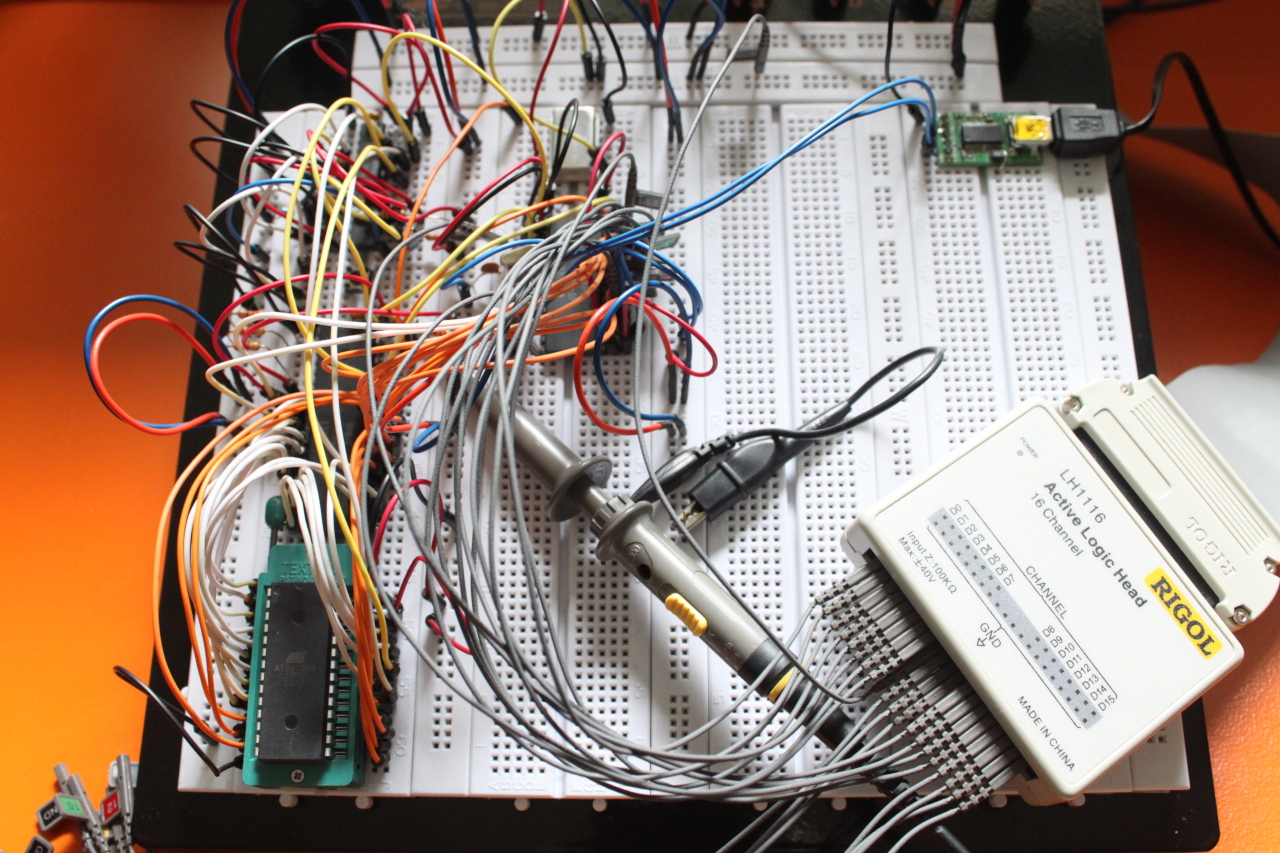
At the center you can see the ACIA 6551 and at the upper right a RS232 to USB adapter board connected to the TXD and RXD pins of the ACIA.
Measurements
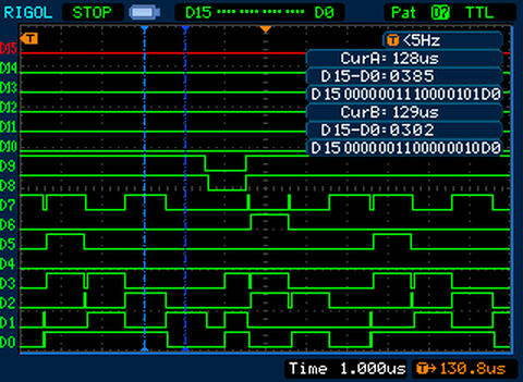
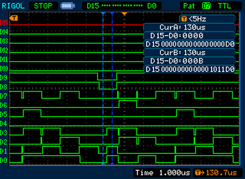
After connecting /OE and /CE of the EEPROM to /CS_ROM, i first checked if everything is still working. I'm using a short code sequence that writes an initialization byte into the ACIAs command register:
ACIA_COMMAND = $0002
lda #%00001011
sta ACIA_COMMAND
In the following diagrams D8 is connected to A15 and D9 to R/W. The first image shows the execution of the LDA operation and the second and third ones the execution of the STA operation. On the third image you can see the actual transfer of the byte $0b into the address $0002. A15 and R/W are low during this transfer and $0b is put on the data bus in the second half of the clock cycle:

Hello World!
No we are ready to run our first real hello world program. At the label main, the ACIA is initialized to the typcial serial settings of 8N1 and 19200 baud. At the label write the characters of the string "Hello World!\r\n" are written into the transmitter data register and transmitted over the serial line. We need to wait until the transmitter data register is empty before we can send the next character. Finally at the label read we wait until a character was sent to the ACIA. Then we jump back to write where "Hello World\r\n" is printer again.
                 .setcpu "6502"

                 ACIA_DATA = $0000
                 ACIA_STATUS = $0001
                 ACIA_COMMAND = $0002
                 ACIA_CONTROL = $0003

                 .segment "VECTORS"

                 .word   nmi
                 .word   reset
                 .word   irq

                 .code

reset:           jmp main

nmi:             rti

irq:             rti

main:
init_acia:       lda #%00001011				;No parity, no echo, no interrupt
                 sta ACIA_COMMAND
                 lda #%00011111				;1 stop bit, 8 data bits, 19200 baud
                 sta ACIA_CONTROL

write:           ldx #0
next_char:
wait_txd_empty:  lda ACIA_STATUS
                 and #$10
                 beq wait_txd_empty
                 lda text,x
                 beq read
                 sta ACIA_DATA
                 inx
                 jmp next_char
read:
wait_rxd_full:	 lda ACIA_STATUS
                 and #$08
                 beq wait_rxd_full
                 lda A CIA_DATA
                 jmp write

text:            .byte "Hello World!", $0d, $0a, $00
If we connect a FTDI232 USB connector to our workstation, start a terminal programm and turn our 6502 computer system on, the hello world message should appear in the terminal window. Press any key and the message is repeated.
$ picocom --b 19200 /dev/ttyUSB0
Terminal ready
Hello World!
For completeness' sake, here is the hexdump of the current firmare:
00000000 4c 05 80 40 40 a9 0b 85 02 a9 1f 85 03 a2 00 a5 |L..@@...........|
00000010 01 29 10 f0 fa bd 2b 80 f0 06 85 00 e8 4c 0f 80 |.)....+......L..|
00000020 a5 01 29 08 f0 fa a5 00 4c 0d 80 48 65 6c 6c 6f |..).....L..Hello|
00000030 20 57 6f 72 6c 64 21 0d 0a 00 00 00 00 00 00 00 | World!.........|
00000040 00 00 00 00 00 00 00 00 00 00 00 00 00 00 00 00 |................|
*
00007ff0 00 00 00 00 00 00 00 00 00 00 03 80 00 80 04 80 |................|
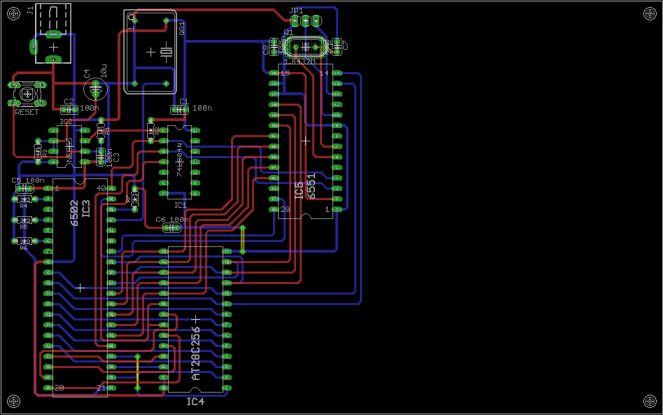
00008000PCB