Sunrise Alarm Clock
A wake-up light. Built with Elixir and Nerves. Running on a Raspberry Pi Zero.
The Hardware | The Software | Testing
This is a wake-up light that simulates the sunrise by gradually increasing the brightness of its LED lamp during a configurable span before the alarm time.
In theory this should stimulate your body to wake up in the morning in a more pleasant way, instead of being torn from sleep by a loud alarm bell. Works for me, but maybe not for you, since everybody is a different kind of sleeper.
These wake-up lights are produced by a number of manufacturers, but here we are building our own using a Raspberry Pi, a handful of electronic components, the programming language Elixir and Nerves , an Elixir framework for developing embedded systems.
Elixir is a functional language and allows us to easily spawn a separate process for each component in our hardware design. If a process fails, it will be automatically restarted by one of our supervisor processes. This enhances the testability and the reliability of our embedded systems. Nerves abstracts from the underlying hardware, which improves testability even more, by allowing us to replace the real hardware modules with simulated ones. Nerves also contains a complete build chain, that generates a Linux image which can be directly copied onto an SD card.
The firmware for this project is described in more detail on the next page .
 Project Files
All of the project files (schematic, PCB layout, firmware source code) are hosted on GitHub:
https://github.com/grappendorf/sunrise-alarm-clock
Hardware parts list for this project
- Raspberry Pi (Zero)
- HD44780 based LCD (16x2)
- PCF8574 I2C 8-Bit IO-Expander (for the LCD display) (Datasheet)
- PCA9530 I2C LED dimmer (Datasheet) (or similar)
- Seeed Grove touch sensor (Product Page)
(The first version of the Sunrise Alarm Clock used a CAP1293 I2C Touch sensor (Datasheet) , see below) - White LEDs
- 12V to 5V DC-DC converter
- 4 push buttons
- 10k potentiometer
- some resistors and caps
- USB to serial converter
Schematics
The circuit is quite simple. Every IO device (except for the buttons) is connected to the I2C bus. The buttons are connected directly to GPIO pins (with pull-up resistors). The 16x2 display is controlled by the PCF8754 IO expander. A metal plate at the back of the wake-up light is connected to metal pad of the Seed Grove touch sensor. The LED0 open collector output of the PCA9530 directly controls the backlight LED of the display. LED1 is inverted by a BC547 (choose any npn low power transistor you like) and then drives a TIP110 power transistor (choose any npn power transistor you like). The current through the LEDs and the TIP110 is limited with a >= 1W resistor (i'm simply using some 1/4 W resistors in parallel). The exact value of this resistor depends on the type of LEDs you are using. In my case 3 white LEDs are connected in series (and 8 of these in parallel). The voltage drop across the resistor is ~3V and i chose the current to be ~200mA. So in my case a 15 Ohm resistor did the job.
Optionally you can connect a USB to serial converter to the RX/TX pins of the Raspberry Pi. You can then use a terminal program like picocom to get access to a shell and don't need to connect any monitor or keyboard.
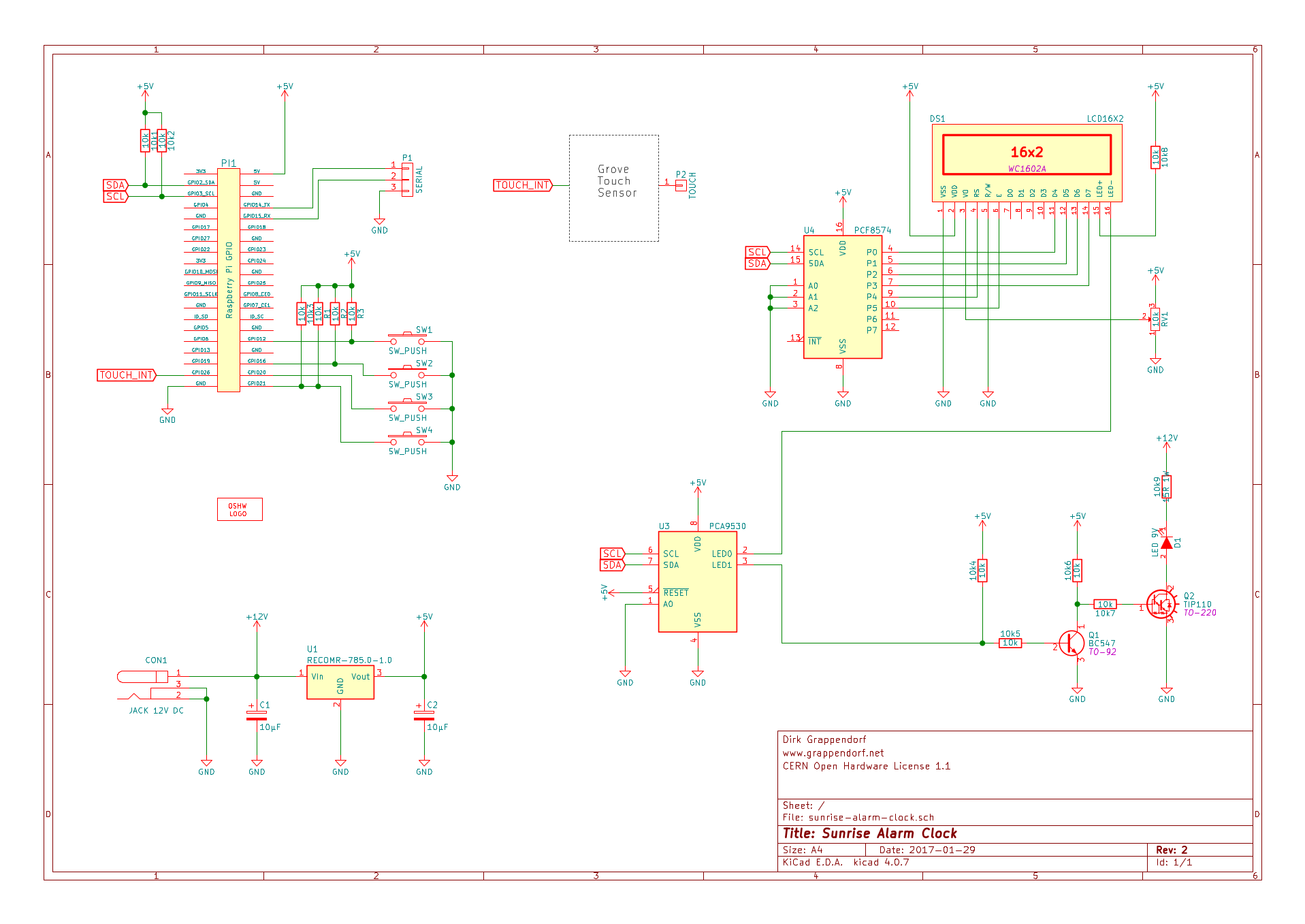
The KiCad schematic files can be found in the sunrise-alarm-clock-kicad sub-directory of the projects GitHub repository .
Adapter Boards for CAP1293 and PCA9530
The PCA9530 is contained in a TSSOP8 package that can easily be soldered on an adapter PCB. I've mounted this chip on small perfboards with pin headers that fit into a breadboard, and later into standard socket headers (you can also get prefabricated adapter boards from suppliers like Adafruit or Sparkfun).
Seeed Grove Touch Sensor
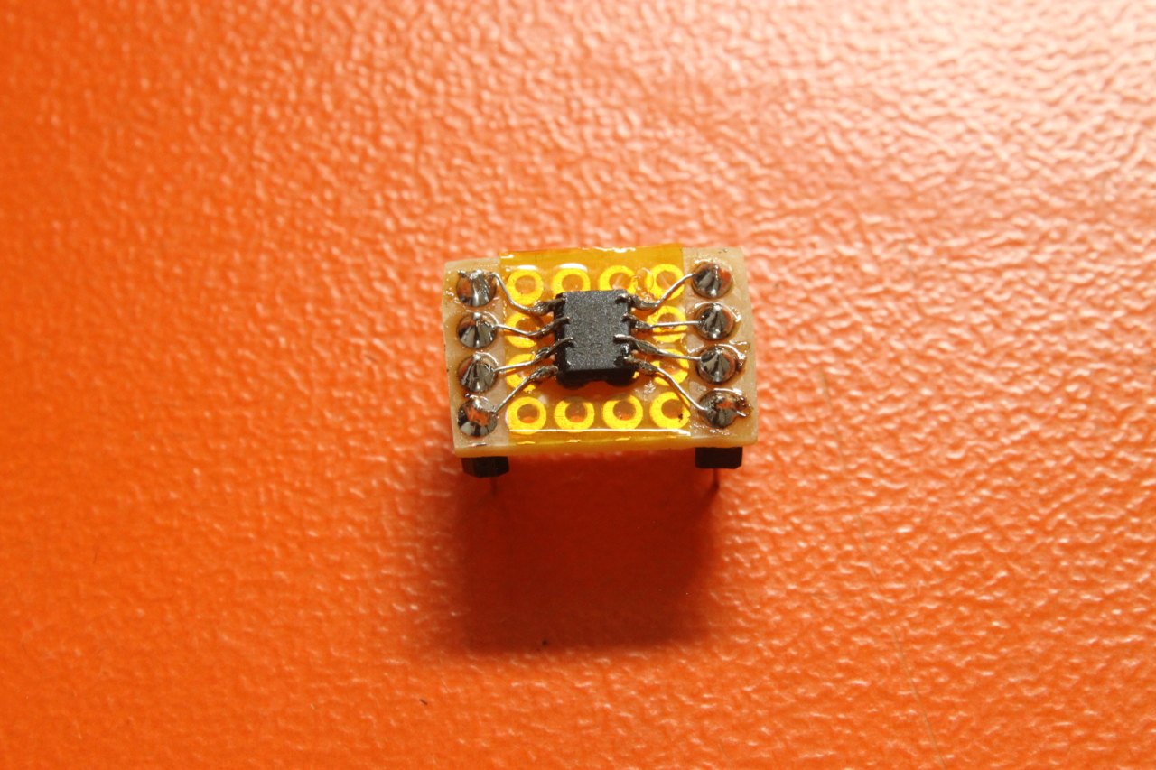
In the first version of the Sunrise Alarm Clock I used a CAP1293 touch sensor chip. The CAP1293 is only available in a tiny TDFN package (2mm x 3mm) and it was quite a challenge to mount it on a custom breakout board:
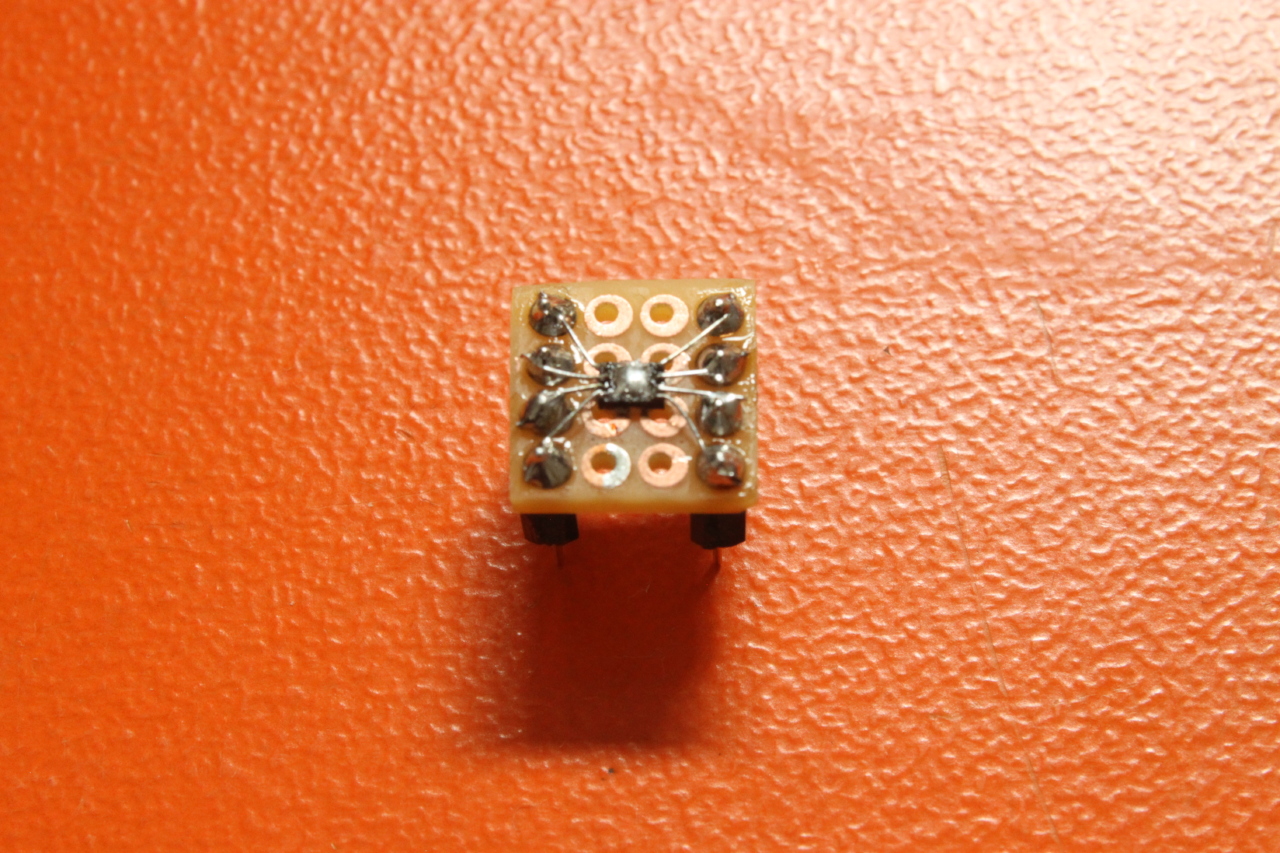
This chip can be seen in all the images below. At some point in time it died and instead of replacing it with another CAP1293, I decided to completely replace it with a Seeed Grove touch sensor module:
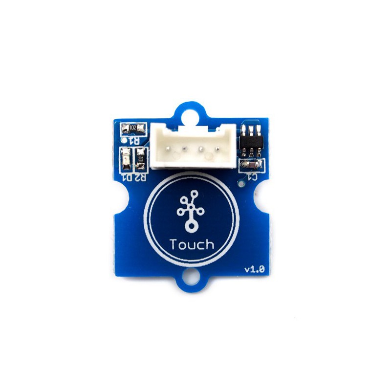
This module is very cheap and only needs a simple connection to a GPIO pin to signal a touch event.
Prototyping
The above circuit is the result of an incrementally enhanced prototype built on a breadboard.
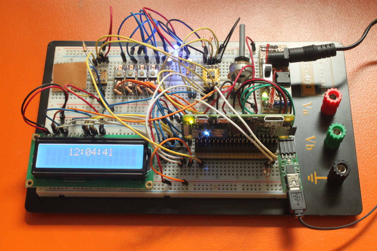
Final Build
PCB
I didn't bother to layout and create a PCB for this project. If you have such a small number of connections and only a handful of components, it is much faster to simply put everything on a perfboard. And since i already soldered the SMD parts onto adapter boards, standard header sockets can be used to hold these chips.
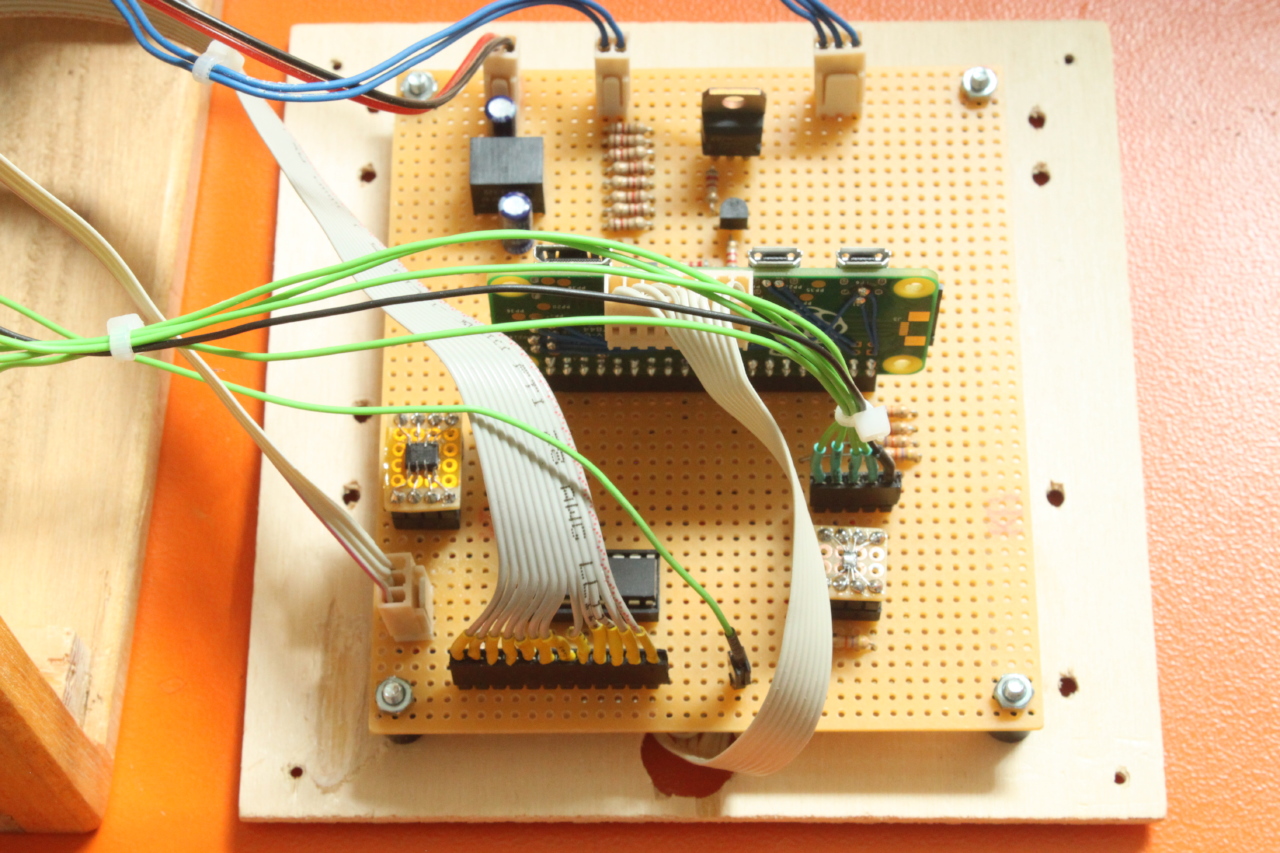
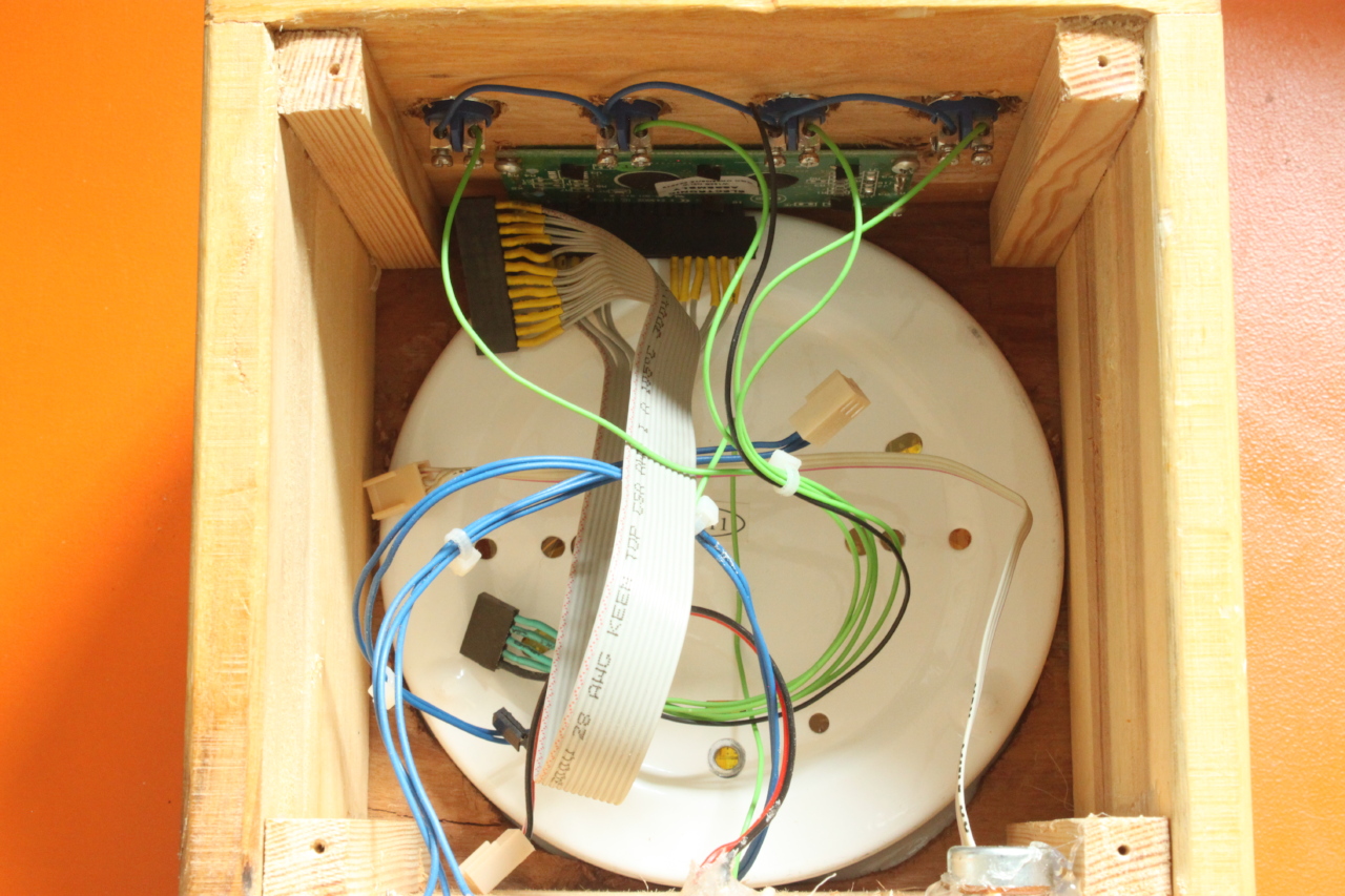
The big connector on top of the Raspberry connects to a SD card holder on the bottom of the clock. Sometimes i had trouble to update the firmware over WLAN. So i wanted a way to replace the SD card without opening the clock case.
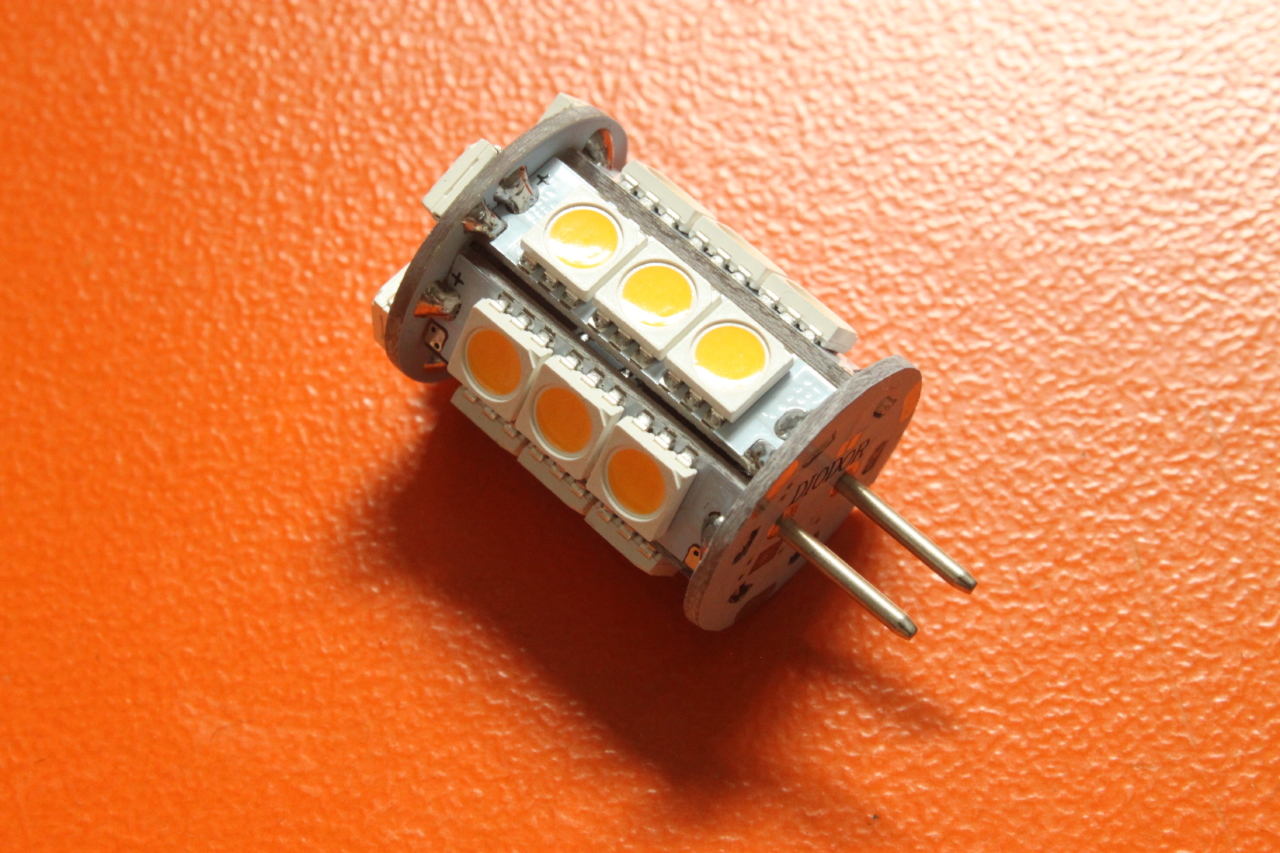
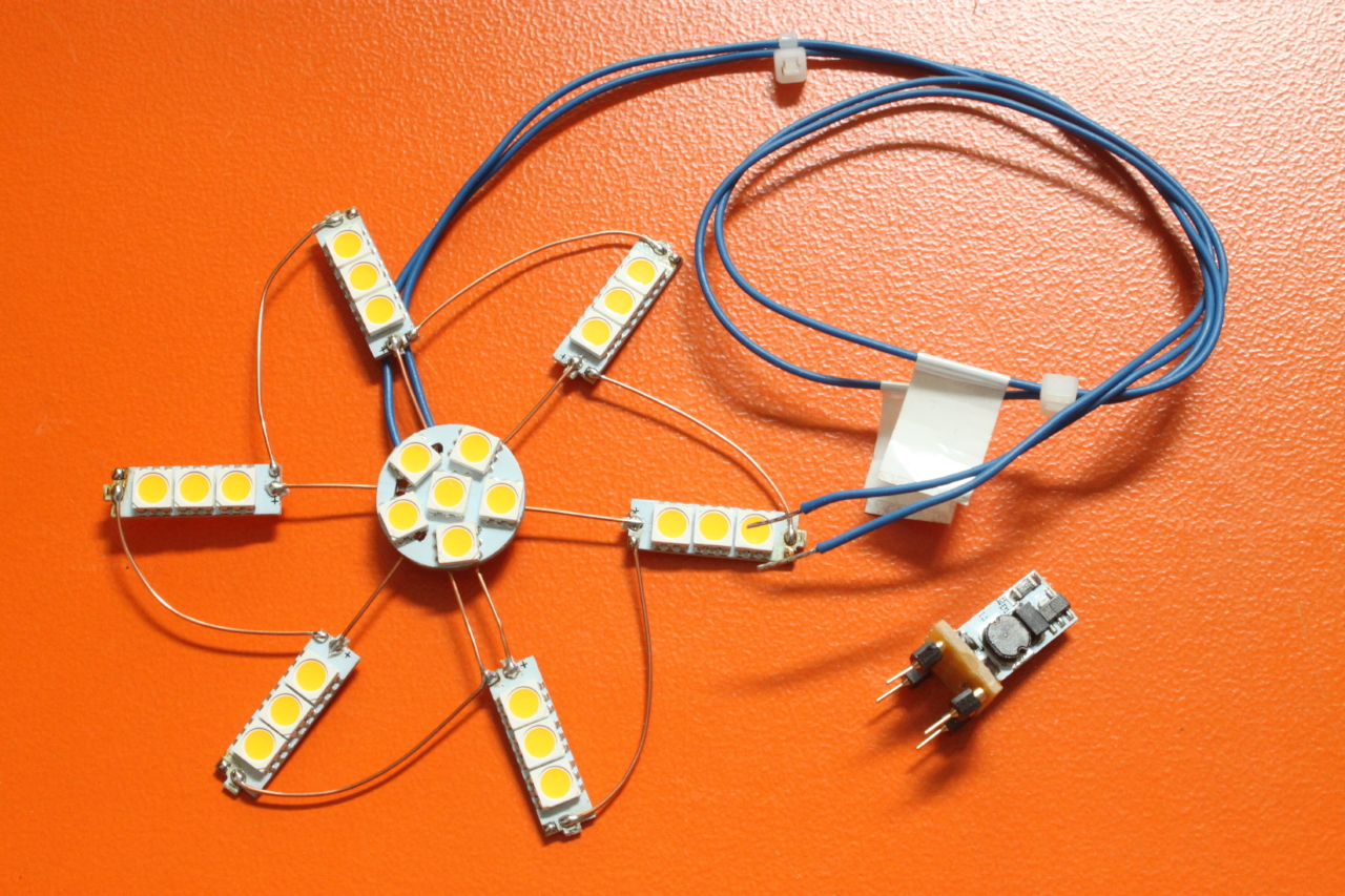
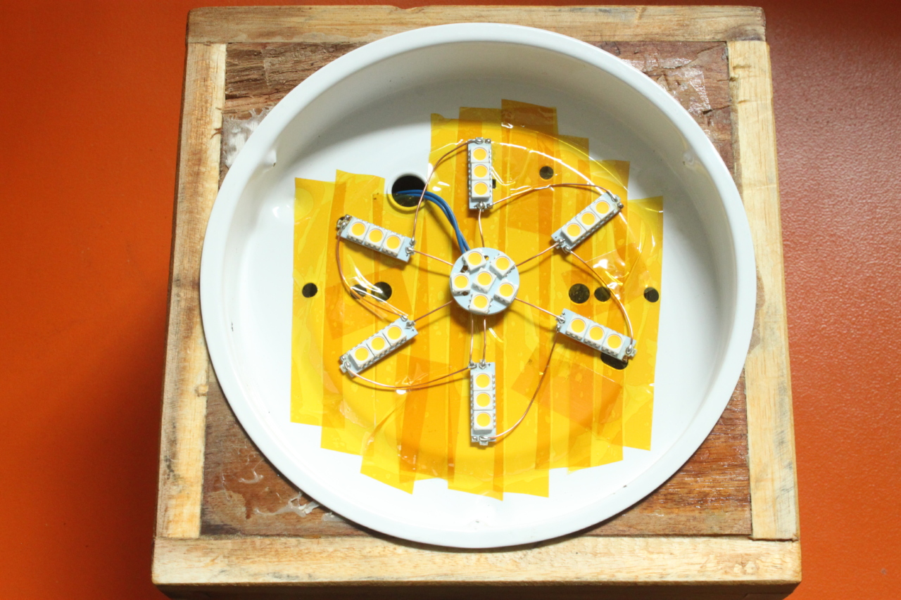
LED light
I destructured a 12V LED lamp so that it fits nicely into the flat wall lamp. The constant current circuit was salvaged, but not used in this project.
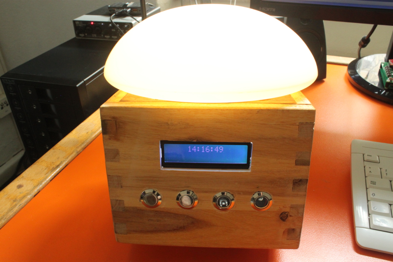
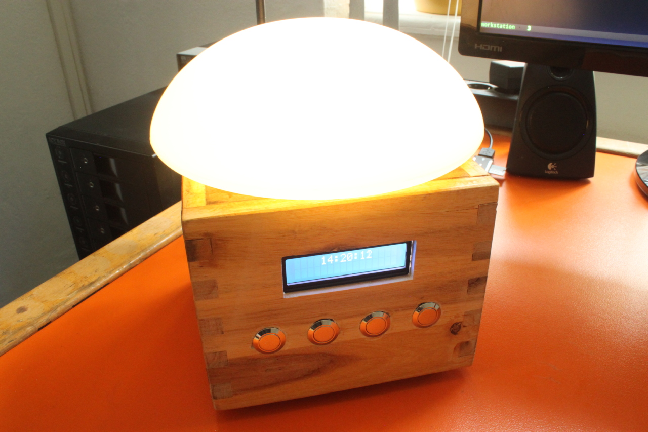
The final result
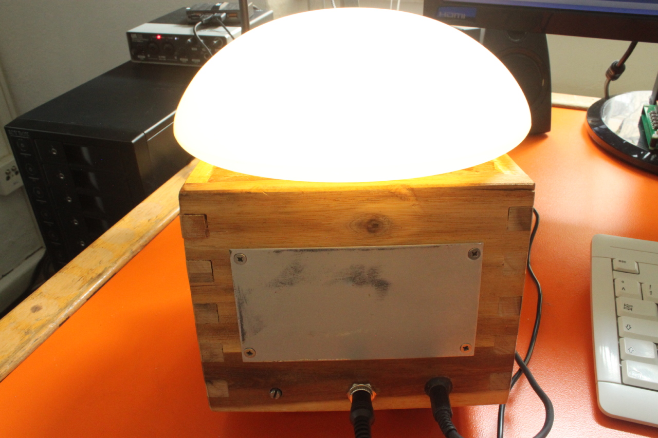
I put everything in a wooden case. The wall lamp goes on top. The Display and four big buttons to the front. The back contains a connector for the 12V wall plug power supply, the serial port connector, the contrast potentiometer and a metal plate for the touch sensor.